
Kit-Style 3D Printer Design
Creating a kit-style 3D printer, optimizing for cost and ease of assembly that improves upon the weaknesses of the kit-type printers that are currently on the market. The final design using a polar coordinate system and PVC joints allow for quick assemble times and low manufacturing cost.
B A C K G R O U N D
Prior to the development of 3D printers, 3-dimensional models were created by subtracting from bulks of material to form desired shapes. Although subtractive processes are still widely used, recent innovations allow for the creation of 3-dimensional designs additively, using only the amount of materials necessary for the desired shape. The additive method forms the basis for 3D Printing.
3D printing was first attempted in 1981 at the Nagoya Municipal Industrial Research Institute by Hideo Kodama [1]. Kodama developed photopolymer 3D printing in which “a vat of photopolymer material is exposed to a UV light that hardens the [3D model]”

Fig. 1: Early 3D Printer US Patent US5121329A
O B J E C T I V E
layer by layer [2]. Since its first development, 3D printing has assisted scientists and engineers in applications of medicine, prosthetics, automation, aerospace, and other relevant fields [3]. 3D printers now encompass other unique forms including, but not limited to, stereolithography, fused deposition modelling, selective laser sintering, selective laser melting, electron beam melting and laminated object manufacturing [4]. Lately, 3D printing has become more accessible to an average user with the refinement of fused deposition modelling (FDM), where filament is melted and extruded onto a build plate in an additive manner. Many retailers now sell kit-type 3D printers which consist of a set of parts to be assembled by the user into a functional printer.
The focus of the project is to develop a functional design of a 3D printer suitable for “home usage.” As opposed to industrial-grade 3D printers intended for the manufacturing of durable and functional parts and mechanisms, home-use printers are intended for small-scale print jobs. Although many of the aforementioned methods of 3D printing are favoured in industry for superior print resolution and print speed, factors such as high cost, large product dimensions and safety hazards, due to lasers and uncured resin, prevent these methods from penetrating the at-home market [5]. Instead, the most common 3D printing technique found in home-use printers is FDM [6]. The FDM process involves the melting and extrusion of filament material onto a build plate, building the print job in thin successive layers [6]. Therefore, the development of the specifications and the design generation process will be focused on implementing the FDM technique as it is relatively more cost-effective and safer for home-usage 3D printers.
In addition to being commercially available, the 3D printer is required to be “kit-type” in nature. A kit-type 3D printer consists of a set of parts to be assembled by the user. Along the vein of home-usage printers, kit-type 3D printers have lower print resolutions, print speeds, and product lifespans, but are relatively lower in cost. Thus, the goal of the project is to develop an assemblable and cost-effective 3D printer design that improves upon the weaknesses of the kit-type printers that are currently on the market.
In particular the device
-
Must output a 3D object created through additive manufacturing
-
Must be able to move in 3 dimensions
-
Must be easily assemblable from a given kit of parts, but must not impact mechanical properties
-
Should not exceed these dimensions: 74 cm (height) by 122 cm (width) by 61 cm (depth)
-
Should maximize printing space based on printer dimensions
-
Should minimize cost without compromising basic requirements
-
Should resist wear
C A N D I D A T E E V A L U A T I O N
Candidate A: Belt Drive Mechanism

This design follows a rectangular coordinate system. It consists of belt drive mechanisms that move the extruder in the X and Y directions, and a jack that moves the build plate in the Z direction. Specifically, there are two rods that go through the housing of the extruder in a crossed formation, and rest on the frame. These rods support the extruder housing which contains a motor that feeds in the filament material for the print. The four ends of these rods are connected to belt pulleys that mesh with four belts, two in the X-direction and two in the Y-direction. These belts are offset from the frame and each mesh with another belt pulley that is connected to a motor. As the motors rotate the belt pulleys, the rotational motions are transmitted into the linear motions of the belts; this allows the extruder to move in the X and Y directions. Meanwhile, a jack beneath the build plate, which is connected to a motor, converts the rotational motion inputted by the motor into the linear
Fig. 2: Belt Drive Mechanism Candidate A
motion of the build plate in the Z-direction. It can also be noted that frame of the design is rectangular and consists of shafts that are connected using three-way elbows.
However, the disadvantages of this design is that there are multiple belt drives and moving parts which introduce wear easily. Belt drives also need to be in tension for maximum transmission and over time this tension is not guaranteed. The added jack limits the movement in the z-direction; how high the platform can go up depends on the length of the linkages and the higher it goes the more unstable it will be.
Candidate B: Polar Coordinate System (T-Bar)
This design follows a polar coordinate system. It consists of an upside-down T-Bar with a linear track that constrains the movement of the extruder in the radial direction. The movement in the angular direction is achieved by the rotation of the T-Bar. At the top-end of the upside-down T, a bevel gear is
attached to its shaft, which is rotated by the second bevel gear via a motor. The Z-direction motion is achieved by a pair of lead screws. A lead screw is composed of a threaded rod and an internal spur gear. The internal spur gears are attached to the build plate and mesh with the threaded rods; as the lead screws are rotated by separate motors, the plate moves up and down. External frames add support to the structure, alleviating the load placed on the lead screws. The cross-sectional image of the linear track is shown in Fig. 4. Two wheels run on each side of the track, but only one wheel is driven by a motor. The second wheel on the opposite side of the track is added for weight balance. The extruder sits inside the housing and is driven by the two wheels on the linear track.
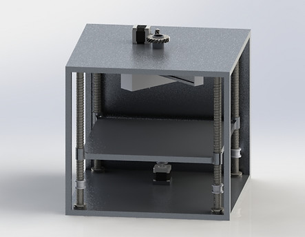
Fig. 3: T-Bar Design Candidate B
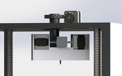
One disadvantage for this design is that it is much larger than Candidate A and is more prone to wear due to the rotation of the 2 threaded rods. The nozzle attached to the linear rail introduces high angular momentum and may cause a decrease in print quality. The novel t-bar design is more prone to structural failure as the moment arm at the extremities is large.
Fig. 4: T-Bar Extruder Housing
Candidate C: Parallel Manipulator Mechanism
_JPG.jpg)
Candidate Design C utilizes a parallel manipulator mechanism that permits extruder head motion with 6 degrees of freedom. This parallel manipulator mechanism consists of 6 linkages and 3 turning pairs. Three belt pulleys that each engage with a belt are actuated independently using motors, moving the three linkages of the manipulator that are connected to the belts, in the Z direction. As these linkages move in the in the Z direction, they move the other three linkages, by means of the turning pairs. Through the linkage system, the extruder can move freely in the horizontal plane. For support, the belt drives are housed within open-faced vertical rods that are fixed to the printer base.
One problem with this is that the pulley system is difficult for the user to assemble. The pulleys are also wear parts and will be difficult to change out.
Fig. 5: Delta Coordinate Design Candidate C
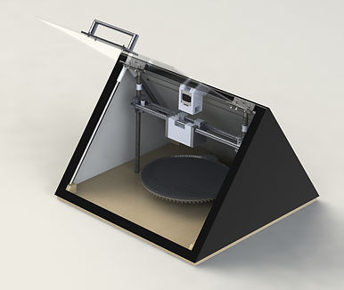
Final Candidate: Polar Coordinate Design with Modifications
_JPG.jpg)
_JPG.jpg)
Fig. 5: Final Candidate Design with Polar Coordinate Rotating Plate and Side-to-Side Belt Extruder
The final iteration of the design uses a polar-coordinate based extrusion system, executed by the coordination of three independent motors: one for manipulating each of the three directions—radial, angular and Z. Their combined effect accurately positions the extruder head to the desired locations on the build plate.


The base of the design consists of a rotating, circular build plate on which the extruder builds the print job. This rotation is accomplished through a motor-driven spur gear that engages with an another spur gear fixed to the underside of the build plate. The engagement of the gears reduces the rotational input speed provided by the motor and increases the torque to rotate the build plate.
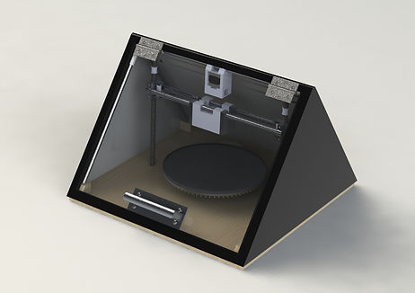
To position the extruder in the desired vertical location, a motor attached to the upper frame of the printer drives a sprocket that engages with a belt drive. This belt drive actuates two parallel lead screws, rotating them simultaneously. Depending on the direction of their rotation, the internal spur gears that are attached to horizontal rods which support the extruder, are able to travel up or down the threaded rods.
Finally, in order to move the extruder closer and further away from the centre of the circular build plate, our design makes use of a belt drive. A sprocket is directly attached to the extruder and sits on the belt which is rotated by a motor, positioning the extruder at a desired radial location. Fig. 7 shows an exploded view of extruder with extruder housing. The extruder housing has holes in the top of the housing in which the rods will pass through. The clearance for the holes will be bigger than the rods meaning that the extruder housing can slide on the rod when moved by the belt drive.
Fig. 6: Rotating Base, Threaded Rod, and Pulley Mechanism Drawing
Fig. 7: Exploded View of Extruder Housing
The final design is supported by a series of metal rods that are fixed together, by the user, into a triangular prism shaped frame. Three-way PVC elbow joints are used to snap-fit the metal rods to each other. The base face of the frame consists of a plate with extruded holes that indicates where the components of the design must be located; the plate stabilizes the components by snap-fitting them into dedicated slots. Note that four blocks, which contain angled holes, extrude out at the corners of the base, to allow easy assembly of the triangular prism shape. In order to support the lead screws on either side of the build plate, ball bearings are press-fit to the lead screws on both ends.
The 3D printer components and its frame sit inside a triangular prism shaped exterior casing that was added for safety and additional support for the entire structure. The exterior casing and the four blocks extruding out of the base are screwed together, alleviating stress concentrated on the printer frame and distributing load. The exterior casing protects the user from moving parts during the printing process.

Fig. 8: Structural Support for Filament Extruder and Z-Direction Mobility
The front face of the triangular prism consists of a transparent Plexiglass sheet that is hinged to the rest of the exterior casing, and a handle bar. This allows the user to supervise the printing process and access the model after the 3D printing process has finished. Furthermore, a slot has been created on the back face of the exterior casing, in order to allow filament to be fed from the exterior of the casing and placed inside the extruder.
F I N A L D E S I G N J U S T I F I C A T I O N
A gear pair is a better mechanism choice than a planetary gear system since the build plate does not require significant torque to be rotated. There is a minimal advantage in producing high torque transmission efficiency through using a planetary gear system since the planetary gear system is harder to assemble, more expensive, and is difficult to maintain. Lower cost and easier assembly could be achieved through the use of a gear pair, satisfying goals C and F of the Engineering Specifications.
A triangular prism shaped exterior frame is an obvious choice as using a cuboid structure would have no structural or spatial advantage in comparison to the triangular prism. A triangular prism structure will require less rods than the cuboid structure, lowering cost and making the design easier in terms of assembly. This advantage satisfies goals C and F of the Engineering Specifications.
Although belts have to be replaced due to stretches and wear, belts are a low-cost solution to motion transmission of the extruder and the placement of the belt is easily accessible. A tensioner was not included in the design since there is already a high contact ratio of the belts, and the extruder which is moved by the timing belts does not add a significant amount of weight. Since the central aim of the design is to create a low-cost solution in comparison to sophisticated industry models, a belt drive should be sufficient.
The belt for the lead screws will need to handle a moderate to high torque, as it will be transmitting the motion from the motor to the threaded rods, which need moderate torque to rotate. Meanwhile, the belt for the extruder’s movement in the radial direction must tolerate high speeds. Therefore, the timing belt is the most suitable option given that it does not slip, does not require much maintenance, maintains its efficiency at high speed and torque, and is cost effective.
Lead screws are chosen because there are less parts required for the lead screws than using a jack or a linear drive. Since ease of assembly should be emphasized in a kit-type printer, the lead screws are a perfect choice. Also, less parts mean lower cost. Therefore, choosing lead screws satisfies C and F of Engineering Specifications.
As the rotation of the platform and the lead screws need moderate to high torque, but not necessarily high speed, the more cost effective stepper motor option is more suitable. For the movement of the extruder in the radial direction, although higher speed is required, high torque is not, so torque degradation is not necessarily disadvantageous. Therefore, a stepper motor is more suitable for more precise positioning
C O N C L U S I O N
All in all, as the justifications show, choices for each mechanism and component were made in attempts to solve the engineering problem posed in the problem statement: to develop an assemblable and cost-effective 3D printer design that improves upon the weaknesses of the kit-type printers that are currently in the market. In order to determine the extent to which printer solves the given problem, the final design was evaluated against the engineering specifications that were developed and also to the benchmark previously outlined. The Kit-CAD meets the engineering specifications in the following ways:
-
Fused deposition modelling is an additive manufacturing process.
-
Use of 3 independent motors permits movement in 3 directions (angular, radial and z).
-
Design meets 6 out of 10 Design for Assembly Principles.
-
Design is compact and can fit on top of the typical desk, having dimensions of 61.37 cm (length) by 61.00 cm (width) by 42.80 cm (height)
-
Print volume as a percentage of total printer volume is increased to 54.68% (as compared to the benchmark design of 16.48%) (Appendix E)
-
Total cost estimate is $651.88, a reduction in cost from the benchmark design of $97.12
-
Number of high-wearing parts were reduced to 15 (2 gears, 4 belt pulleys, 2 belts, 2 bushings and 5 bearings)
By performing better than the chosen benchmark and meeting the specifications, the Kit-CAD mitigates the weaknesses of the state of the art. Therefore, it is an appealing alternative to kit type 3D printers on the market today.
R E F E R E N C E S
-
“History of 3D Printing: It's Older Than You Think,” Redshift, 09-Oct-2017. [Online]. Available: https://www.autodesk.com/redshift/history-of-3d-printing/. [Accessed: 05-Dec-2017].
-
“Kodama, Hideo and Photopolymer 3D Printing,” Whiteclouds 3D printing. [Online]. Available: https://www.whiteclouds.com/3dpedia-index/kodama-hideo-and-photopolymer-3d-printing. [Accessed: 05-Dec-2017].
-
A. Chowdhry, “What Can 3D Printing Do? Here Are 6 Creative Examples,” Forbes, 08-Oct-2013. [Online]. Available: https://www.forbes.com/sites/amitchowdhry/2013/10/08/what-can-3d-printing-do-here-are-6-creative-examples/#6c67a21a5491. [Accessed: 05-Dec-2017].
-
3dprintingfromscratch.com, “Types of 3D printers or 3D printing technologies overview,” 3D Printing from scratch, 02-Feb-2016. [Online]. Available: http://3dprintingfromscratch.com/common/types-of-3d-printers-or-3d-printing-technologies-overview/. [Accessed: 05-Dec-2017].
-
“State of the Industry,” business.com. [Online]. Available: https://www.business.com/categories/best-industrial-3d-printers/. [Accessed: 05-Dec-2017]
-
E. Palermo, “Fused Deposition Modeling: Most Common 3D Printing Method,” LiveScience, 19-Sep-2013. [Online]. Available: https://www.livescience.com/39810-fused-deposition-modeling.html. [Accessed: 05-Dec-2017].
-
“10 Best Cheap 3D Printer Kits under $750 - Best of 2017,” 3D Printing, 15-Nov-2017. [Online]. Available: https://3dprinting.com/3dprinters/cheap-3d-printer-kits/. [Accessed: 05-Dec-2017].
-
“Original Prusa i3 MK3 kit,” Prusa Research. [Online]. Available: https://shop.prusa3d.com/en/3d-printers/180-original-prusa-i3-mk3-kit.html. [Accessed: 05-Dec-2017].
-
“Original Prusa i3 MK3 3D Printer - Price - Compare - Reviews - Specs,” 3D Printing, 15-Nov-2017. [Online]. Available: https://3dprinting.com/pricewatch/3d-printer/original-prusa-i3-mk3-fully-assembled/. [Accessed: 05-Dec-2017].
-
“Nema 17 Stepper motor,” Build A 3D Printer, 23-Sep-2015. [Online]. Available: http://builda3dprinter.eu/product/nema-17-stepper-motor/. [Accessed: 05-Dec-2017].
-
“The All-New MakerBot Replicator Mini ,” The MakerBot Replicator Mini | MakerBot. [Online]. Available: https://www.makerbot.com/replicator-mini/. [Accessed: 05-Dec-2017].